
DELTA XS V5 QUICK GUIDE
-edited.jpg)
I. Specifications

1. Moving base dimension
With 3 axis model, the moving base just simple as 6 M4 holes.
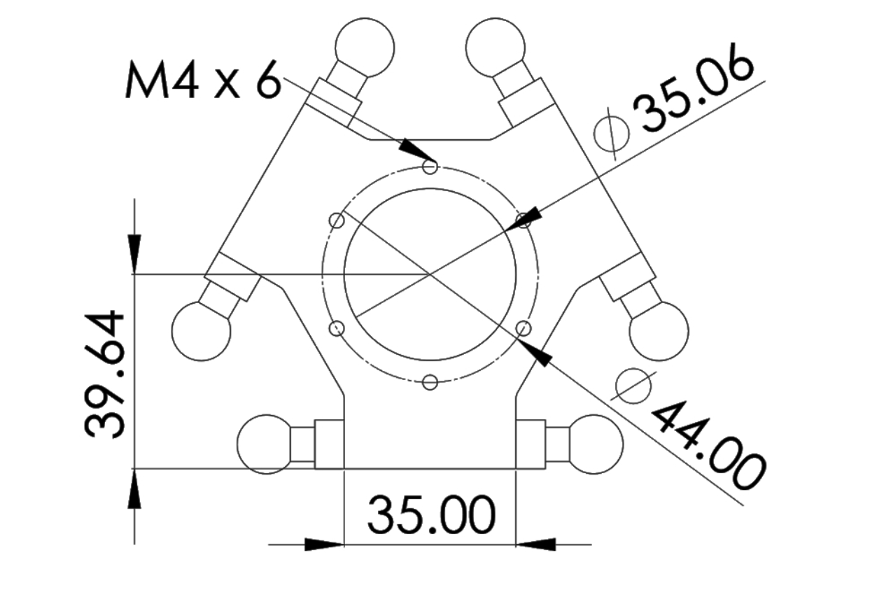
The moving base for the 4-axis model:

For the 5-axis model: And 6-axis model:

For the 5-axis model:And 6-axis model:


2. Working space

3. Robot holder flat & Safe working space
4. 3D Working space preview

II. Pinout & Communications

1. POWER SUPPLY
+ 24VDC / 16A ~ 384W
2. Communication Interfaces
USB0: USB protocol standard, this port can be use to update firmware.
USB1: another USB standard, which isolated with all other power supply.
RS232: RS232 protocol port with TX as pin 2, RX as pin 3 and GND as pin 5.
RS485: RS485 protocol port with RX+ as pin 1, RX- as pin 2, TX- as pin 3, TX+ as pin 4, and GND as pin 5.
3. Input & Output
Digital Input:  Input: 24V / 3mA.


Pinout: 1-I0 2-I1 3-I2 4-I3 5-GND.
Analog Input:
Input: 0 - 10V/0 - 4096.
Pinout: 6-A0 7-A1 8-24V 9-GND.
Example:
Digital Output:  Output: 24V / 500mA (Open collector).

Pinout: 1-D0 2-D1 3-D2 4-D3 5-D4 6-D5
7-D6 8-D7 9->15-GND.
Example:
3. E-Stop button
Input: 24V / 3mA
Pinout: 1-GND 2-I5 3-I6 3-24V
If emergency button is not enabled, I4 and I5 can be use as input pin.
Note: Connect any output as shown above, do not load more than 500mA for each output pin.
III. Assemble Guide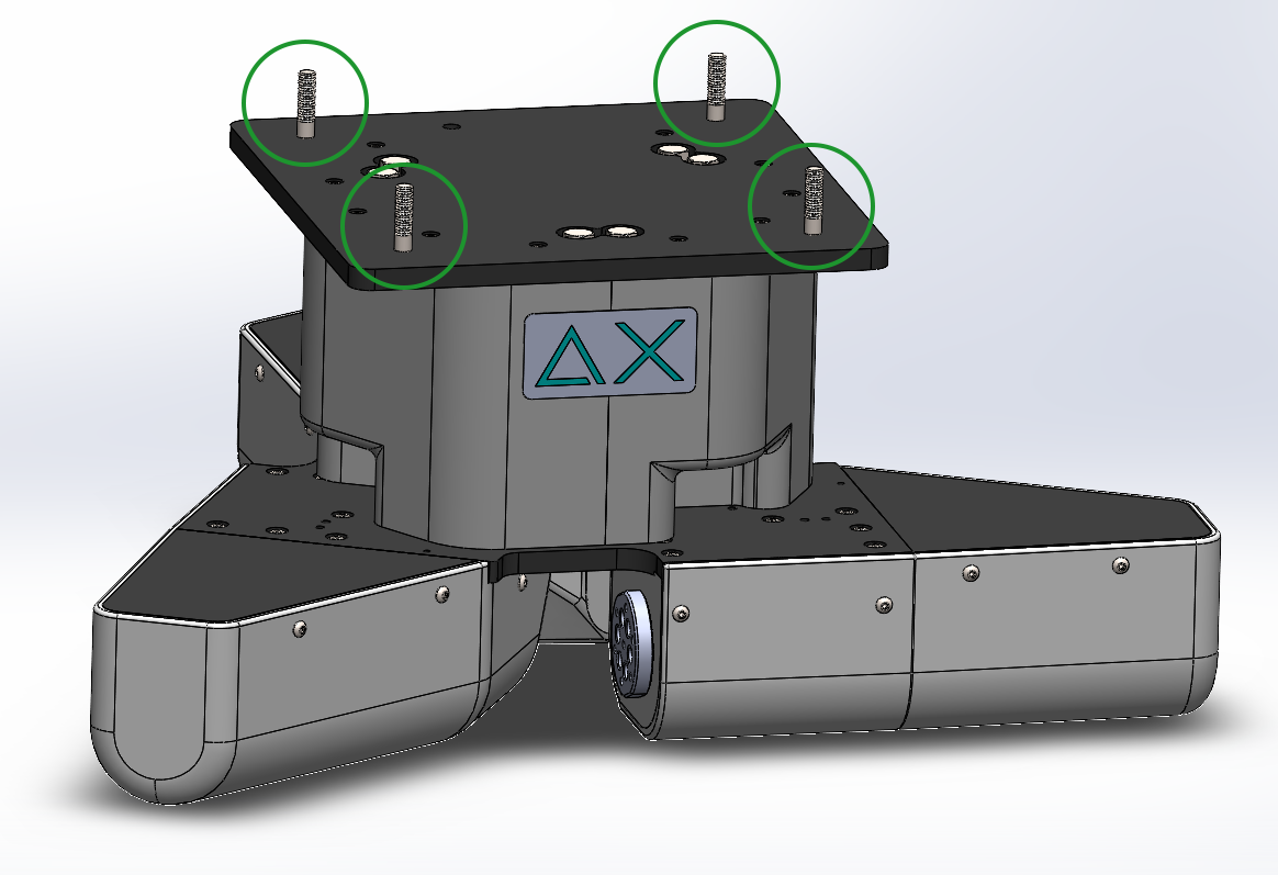
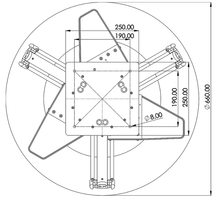
Step 1: Mount the robot body onto the frame
On the base of the robot body, there are four Ø8 holes used for attaching the Delta robot body to the frame. Please use M8 bolts to tighten and secure the robot.
Precaution: When the arm has not mounted yet, do not attempt to rotate the flange.
If you have rotated it passing more than 60 degrees, please stop this step, hang the robot on, wire up the power and homing the robot before installing the inner arm.
Step 2: Home the robot
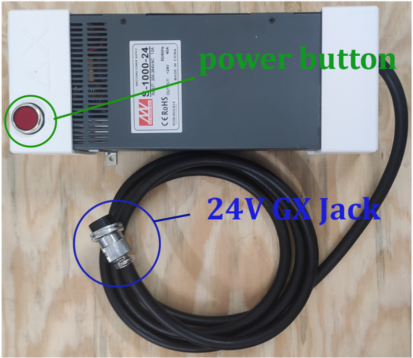
- Connect 24V GX jack in 24V adapter to PWR jack in robot.
- Press the power button if the robot has not power yet, the power led will be on and Status led.

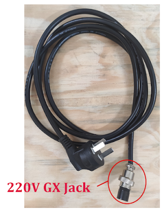
- Connect 220V GX jack to 24V adapter and the other end to the 220V source.

- Connect the USB cord to the panel's USB0 connector, and you can now use the Delta X Software to control robot.
- Download software and install it. After install successfully, launch the software and press Connect button to connect with the robot. If button change to Disconnect that mean robot is connected.
- Press Home button to home the robot.

Step 3: Install Upper Arms
Do not tighten these M5 bolts all at once; only slightly. Once all 6 M5 bolts are fitted, gently press the robot arm downward and tighten all bolts.

Step 4: Install Lower Arms
Pull the outer arm out and place it outside the ball end of the inter arm. Repeat the process with the other 2 arms.

Step 5: Install Moving Base
Pull the outer arm out and place it outside the ball end of the moving base. Repeat the process with the other 2 arms.
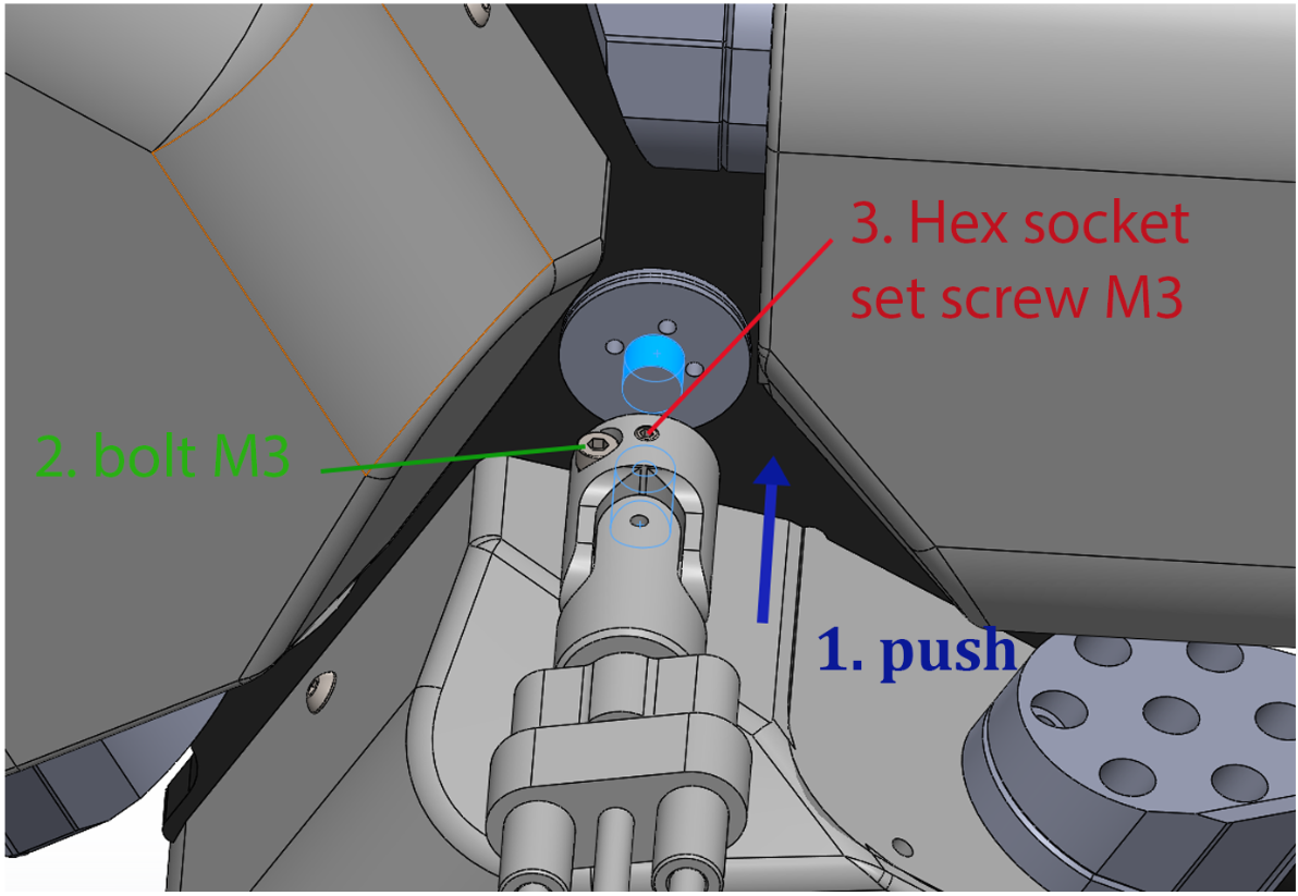
Step 6 (Optional): Install Axis 4
If the robot has a 4 axis, attach the slide rail of axis 4 to the shaft on the body of robot as closed as possible.
Tighten bolt M3 first and then Hex socket set screw M3.